When a system uses removable electronic modules, the packaging problem is not limited to mounting PCBs. The enclosure has to maintain repeatable module spacing, provide a predictable front and rear mechanical interface, protect assemblies during handling, and support practical maintenance over the service life of the equipment. Those details affect fit, serviceability, shielding continuity, connector alignment, and the amount of rework required during integration.
Vector’s CMA module subrack architecture addresses that packaging problem by combining a 19-inch rackmount frame with individually enclosed EFP modules. According to Vector’s published CMA product information, these subracks are intended for rack mounting in the EIA 19-inch format and accept EFP modules in 1.6-inch, 2.0-inch, and 3.0-inch widths, with 4.5-inch width available as an option. In practice, that makes the platform relevant for instrumentation, telemetry, test equipment, and similar systems that need modular, serviceable plug-in assemblies.
The featured image appears at the beginning of the article as required. The image in use is a 16:9-format product image that presents the Vector CMA product as the main subject against a soft laboratory background, which is consistent with the requested visual treatment for a featured image. This article focuses on the verified mechanical characteristics published by Vector and removes any technical, standards, or capability claims that could not be confirmed from available source material.
Why this topic matters
A subrack decision is often treated as a packaging detail late in the design cycle. That is where avoidable problems begin. If module width, rear-interface depth, PCB support method, or service access are resolved too late, the team can end up redesigning panels, relocating connectors, changing cable routing, or revising maintenance procedures after electrical design is already frozen.
For programs in test, telemetry, industrial control, or other high-reliability environments, the subrack becomes part of the controlled system interface. It influences how modules are installed, how quickly assemblies can be replaced, how consistently rear connectors line up, and whether the finished system can be manufactured and serviced without repeated mechanical exceptions.
Rackmount structure based on the EIA 19-inch format
CMA subracks use the conventional 19-inch rackmount envelope. Vector’s published CMA information identifies 3U models with an overall height of 5.25 inches and a CMA15 configuration with an overall height of 7.0 inches. The frame is intended for installation in 19-inch rack systems.
The subrack frame consists of aluminum side panels, front TSW struts, rear bracketed struts, case guides, dress panels, handles, and mounting hardware. The side panels attach to Vector TSW struts, which establish the front mechanical interface for EFP module installation.
This matters because a defined rack interface reduces mechanical improvisation at the system level. Instead of creating a one-off support structure around each electronics set, the design can start from a known rack envelope and then resolve module count, width, rear access, and connector strategy within that boundary.
Practical example: bench prototype to deployed rack assembly
A bench prototype may function correctly when a few assemblies are hand-positioned inside a temporary frame. That same approach often breaks down in a rack-integrated build. The front panel line may become uneven, rear connector access may disappear once adjacent hardware is installed, and extraction clearance may be lost. A structured subrack architecture reduces those variables by fixing module position and front mounting references early.
Aluminum construction and conductive mechanical connections
Vector’s published subrack information identifies aluminum construction for the major structural elements. In this type of assembly, aluminum is typically selected because it supports low-mass rack packaging, practical machining, and repeatable fabricated geometry.
Vector also states that the CMA design uses conductive connections between metal components. That point is important, but it should be interpreted carefully. Conductive construction does not automatically guarantee system-level shielding performance or grounding behavior by itself. Actual continuity across the assembled structure depends on finish selection, masked contact areas, fastener stack-up, surface preparation, and assembly control.
From a design-review perspective, conductive joints should be treated as specified interfaces rather than assumptions. If the program depends on enclosure bonding, shielding continuity, or a defined chassis ground path, those requirements should be documented at the drawing and build-instruction level.
Design and manufacturing considerations
- Confirm whether painted, plated, or otherwise finished surfaces will interrupt intended metal-to-metal contact areas.
- Review whether front panels, side panels, rails, and rear hardware require controlled contact zones.
- Verify that cosmetic finish requirements do not conflict with bonding requirements.
- Include continuity-critical hardware, finish callouts, and assembly notes in the released configuration package.
That discipline helps avoid a common problem: a mechanically correct assembly that still requires rework because the conductive path was assumed rather than defined.
Module widths, capacities, and packaging tradeoffs
CMA subracks are configured around published EFP module widths of 1.6 inches, 2.0 inches, and 3.0 inches, with 4.5 inches listed as an option. Width selection is one of the most important early decisions because it directly sets both module count and available enclosure volume per assembly.
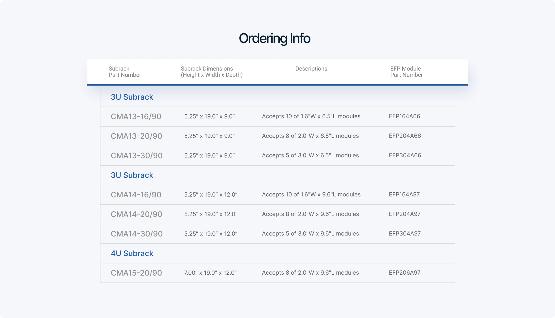
Representative configurations published by Vector include:
| Subrack | Overall dimensions | Module configuration | Capacity |
|---|---|---|---|
| CMA13-16/90 | 5.25 × 19.0 × 9.0 in. | 1.6 in. wide × 6.5 in. long | 10 modules |
| CMA13-20/90 | 5.25 × 19.0 × 9.0 in. | 2.0 in. wide × 6.5 in. long | 8 modules |
| CMA13-30/90 | 5.25 × 19.0 × 9.0 in. | 3.0 in. wide × 6.5 in. long | 5 modules |
| CMA14-16/90 | 5.25 × 19.0 × 12.0 in. | 1.6 in. wide × 9.6 in. long | 10 modules |
| CMA14-20/90 | 5.25 × 19.0 × 12.0 in. | 2.0 in. wide × 9.6 in. long | 8 modules |
| CMA14-30/90 | 5.25 × 19.0 × 12.0 in. | 3.0 in. wide × 9.6 in. long | 5 modules |
| CMA15-20/90 | 7.0 × 19.0 × 12.0 in. | 2.0 in. wide × 9.6 in. long | 8 modules |
These published part-number relationships are useful because they turn module-width selection into a concrete packaging decision rather than a general preference.
Practical example: choosing between 1.6-inch and 3.0-inch modules
A narrower 1.6-inch module width can maximize module count, which may be useful when the system architecture favors many smaller functional blocks. A 3.0-inch module width reduces total slot count but increases the internal mechanical envelope for connectors, components, and cable exits. That tradeoff is often more important than nominal slot quantity, especially when the assembly includes taller components, denser front-panel I/O, or more demanding service access requirements.
The key engineering point is simple: module width should be selected against the real assembly envelope, not only against an abstract channel count.
EFP modules provide enclosure at the circuit-card level
In the CMA architecture, the EFP module acts as an individual enclosure for the electronic assembly before it is installed into the rack-level frame. Vector’s published module description identifies the following kit elements:
- Front panel
- Rear panel
- Side cover panel
- Top and bottom extrusion rails
- Thumb screw
- Mounting hardware
Vector’s documentation also identifies rail grooves for 0.062-inch PCBs. That dimension is approximately 1.57 mm. If the intended board thickness differs, the fit should be reviewed before committing to the packaging approach.
This point matters because module-level enclosure changes the mechanical behavior of the system. Instead of inserting bare cards into a card cage, the design inserts self-contained plug-in assemblies. That can simplify service handling and provide a more controlled mechanical boundary for each function.
Design and manufacturing considerations
- Confirm actual PCB thickness and edge tolerance against the rail groove.
- Review component height and keepout zones against the internal module envelope.
- Check whether connector overhang or wiring exits interfere with cover installation.
- Resolve front-panel cutouts, labeling, and fastener access before release to production.

Thumb-screw retention and service access
The extended EFP front panel provides the front mechanical interface to the TSW strut, and published product information identifies thumb-screw locking for module retention. That arrangement supports module removal without specialized tooling.
From a serviceability standpoint, this is useful where the equipment will undergo board replacement, debug, calibration, connector inspection, or controlled hardware revision changes. The module cover design is also relevant: Vector’s published information states that the cover includes a locking detent and slides out of its groove when released, allowing PCB access without taking apart the full subrack.
Practical example: maintenance access in a populated rack
In a tightly packaged system, maintenance time is often driven less by the failed board itself and more by the amount of adjacent hardware that must be disturbed to reach it. A removable module with front retention and a sliding cover can reduce that disruption, but only if extraction clearance and finger access were planned at the system level.
Rear-panel strategy and rear-interface alignment
Vector’s published information indicates that EFP modules are available with either a solid rear panel or an open cutout-style rear panel. The correct choice depends on how the module interfaces with the rest of the system.
A solid rear panel may make sense when the rear boundary should remain enclosed or when only limited rear provisions are needed. An open rear-panel approach is more suitable when the module must expose connectors or support rear-interface hardware.
Vector also publishes that the CMA rear struts are adjustable and that HD34 and HD34B hardware kits are used to install card-edge connectors on rear-bracketed TSW rails. The published distinction between the two kits is screw length: HD34 uses a 0.50-inch screw and HD34B uses a 0.25-inch screw.
Design and manufacturing considerations
- Confirm connector-body depth and rear cable bend radius before locking module depth.
- Check whether extraction clearance remains available with all neighboring modules installed.
- Review mating-force requirements if rear card-edge or connector engagement is part of installation.
- Ensure rear-hardware selection is carried through to drawings, assembly instructions, and BOM control.
Rear-interface geometry is one of the easiest places to create a late-stage integration problem. If it is left unresolved until after panel and cable designs are complete, the result is often bracket rework, connector relocation, or an avoidable change to module depth.
Mixed-width layouts, filler panels, and enclosure discipline
Mixed-width modular layouts can be useful, but they should not be treated casually. Any unused space at the front of the subrack becomes a real mechanical opening unless it is deliberately closed out. In practice, filler panels help maintain a continuous front boundary and reduce the risk of accidental intrusion into open spaces.
That does not mean a blank panel solves every system-level behavior automatically. Airflow path, contact continuity, adjacent panel construction, and the overall enclosure strategy still have to be reviewed at the assembly level.
For related EIA non-metric architectures, Vector also publishes extrusion rails and accessories, including T-struts, TSW struts, and standalone Frame-Loc rails. The design choice between a CMA/EFP arrangement and a bare-card rail arrangement depends on whether each PCB should remain a self-contained enclosed module or whether a more open card-guide approach is acceptable.

Common mistakes and integration risks
Several recurring mistakes appear when modular subracks are specified too late or too loosely:
- Selecting module width from board count alone without checking real component and connector volume
- Assuming rear connector access will be available after the full rack is populated
- Treating conductive construction as equivalent to fully resolved bonding or shielding behavior
- Releasing panel geometry before extraction clearance and thumb-screw access are reviewed
- Overlooking PCB thickness compatibility with the published 0.062-inch rail-groove requirement
- Allowing mixed-width layouts to create unmanaged front openings or service interference
None of these issues are exotic. They are ordinary packaging errors that become expensive because they are discovered after other parts of the design are already committed.
What Engineers and Program Teams Should Consider
For a CMA-based architecture, the most useful review questions are practical:
-
What is the actual module envelope required?
Check PCB thickness, component height, connector overhang, cable exit path, and cover clearance. -
How will the module be installed and removed in the finished system?
Review extraction path, neighboring hardware interference, and tool access at the front and rear. -
What is the rear-interface strategy?
Resolve rear-panel style, connector location, card-edge hardware, and cable bend requirements before layout release. -
What assembly attributes must be controlled?
Identify finish requirements, conductive contact zones, labeling, hardware variants, and any build notes needed to preserve repeatability. -
Is the subrack being treated as part of the system definition?
The frame, module, panel, connector, and hardware selections should be configuration-controlled together, not as disconnected line items.
A disciplined approach to CMA selection
A reliable CMA configuration begins with interfaces, not just slot count. The primary decisions remain straightforward:
- Rack height and depth: Select the applicable frame height and confirm available module length.
- Module width: Choose width according to real enclosure volume, I/O density, and module count.
- PCB fit: Confirm compatibility with the published 0.062-inch PCB rail-groove dimension.
- Rear interface: Define whether the design needs a solid rear panel, an open rear arrangement, or rear card-edge hardware.
- Conductive interfaces and finish: Specify finish treatments and contact requirements where continuity matters.
- Service access: Define how the module, cover, PCB, and rear hardware will be accessed during test and maintenance.
- Configuration control: Maintain the subrack and its associated module hardware as a controlled mechanical baseline.
Where a program needs more than a loose collection of parts, this kind of packaging discipline supports a cleaner path into manufacturing.
How Vector can help
Vector’s relevance here is not only that it publishes the CMA subrack and EFP module hardware. The practical value is in aligning the rack-level structure, module format, panel approach, and rear-interface hardware around the actual integration requirement. For programs that need a controlled mechanical platform, that reduces the chance that packaging decisions will be deferred until they become production problems.
Where the larger system requires enclosure fabrication, custom panels, backplane integration, or complete assembly to customer specification, the same disciplined approach to configuration control and manufacturable interfaces becomes more important, not less. The mechanical packaging decision should support the finished system build, service process, and revision path.
Conclusion
A modular subrack is only useful when it controls the interfaces that matter. In the CMA context, that means published rack compatibility, defined module widths, known PCB support, serviceable retention, adjustable rear hardware, and deliberate treatment of conductive mechanical interfaces. When those factors are resolved early, the subrack becomes a stable packaging platform rather than a late-stage workaround.
If you need help with a design, manufacturing, sourcing, or system-integration challenge involving modular packaging, contact Vector.